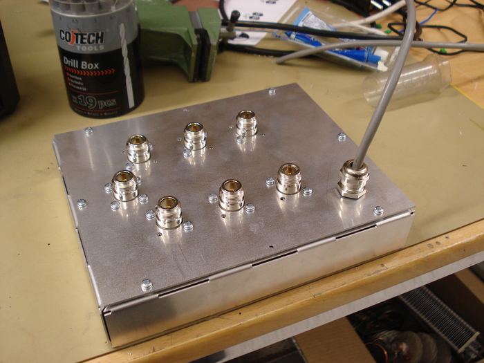
The 6×1 is an antenna switch which has got 6 antenna outputs which can be routed to one radio input. When an antenna output is not used it is grounded which is good against static discharges such as lightning strikes etc.
It has got 0.05dB insertion loss on 28 MHz and on 50 MHz it has got 0.19dB insertion loss. The isolation between ports is about 70dB +/- some dB depending on which port is used.

List compiled by G4AON if ordering from rapid
Top view of the board – If used as a drilling template, make sure to print it as 1:1 scale.
If wanting the low insertion loss mentioned above you need to add an series inductor as shown on the pictures below. If you have an VNA of some sort you can easily adjust it to get the lowest insertion loss. Note though, that the coil in the picture below was optimized for another frequency. If you don’t have any special instruments you can just make an inductor which will make it optimized for 1-30 MHz with the following dimmensions,
2mm copper wire
8mm inner diameter
11mm long from end to end
2.5 turns


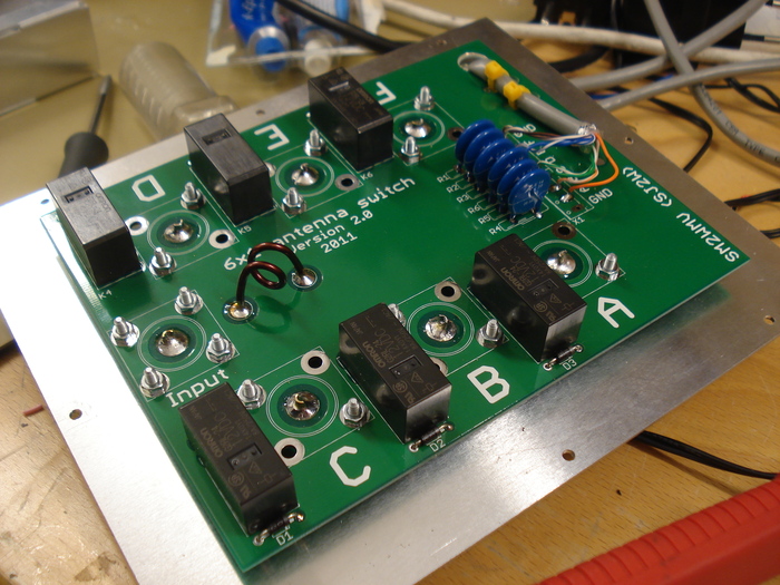
What is the purpose of the coil in the middle of the board?
regards,
SM5OCI Per
There are some extra capacitance in the board from the relays etc which are reduced by adding that coil in series. So it decreases the insertion loss in the design.
This PCB controlled by Arduino:
http://pd9x.nl/2015/08/antenna-switch-controlled-by-arduino-uno/
Laurens PD9X